As in the previous material about VLANs , that one way that can be used to learn the concept of VLANs in computer networks is to use applications. One application that we can use to learn how to configure vlan is to use the cisco package tracer.
In the Cisco package tracer simulation application, we can create a VLAN simulator network. Even though it’s only a simulation, the utilization will be the same when we configure the VLAN with the actual tool.
One example of a VLAN configuration in this Cisco package tracer is to use a single switch. The point is that we do this VLAN configuration only on one switch, which means that the computer network that is formed is centralized on one switch.
The first step before configuring the VLAN switch in Cisco Package Tracer is that we first create a topology and planning table. The goal is to make it easier and more focused in completing a VLAN configuration in Cisco package tracer.
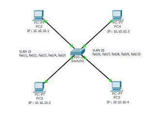
The following is a topology and planning table that we will create in implementing the VLAN configuration on the switch in the Cisco package tracer.

- VLAN 10 consists of ports 1, 2, 3, 4 and 5
- VLAN 20 consists of ports 6, 7, 8, 9 and 10
- The type of cable used from PC to Switch is Straight
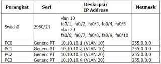
- Look at the planning table below

Steps to Create a Vlan Switch on Cisco
For the steps to configure the vlan switch on the cisco package tracer, we use the CLI language. So the vlan configuration that we do uses the command script. The steps for configuring a VLAN on a Cisco packet tracer with one switch are as follows:
First
Click on the Switch, go to the CLI Tab, type the command below to see the condition of the VLAN on the switch (those in bold are typed).
Switch>enable

Switch#show vlan
VLAN Name Status Ports —- —————————– ——— —————————- 1 default active Fa0/1, Fa0/2, Fa0/3, Fa0/4 Fa0 /5, Fa0/6, Fa0/7, Fa0/8, Fa0/9, Fa0/10, Fa0/11, Fa0/12, Fa0/13, Fa0/14, Fa0/15, Fa0/16, Fa0/17, Fa0/ 18, Fa0/19, Fa0/20 Fa0/21, Fa0/22, Fa0/23, Fa0/24 1002 fddi-default act/unsup 1003 token-ring-default act/unsup 1004 fddinet-default act/unsup
1005 trnet-default act/unsup VLAN Type SAID MTU Parent RingNo BridgeNo Stp BrdgMode Trans1 Trans2 —- —– ———- —– —— —— ——– —- ——– —— —— 1 enet 100001 1500 – – – – – 0 0 1002 fddi 101002 1500 – – – – 0 0 1003 tr 101003 1500 – – – – – 0 0 1004 fdnet 101004 1500 – – – ieee – 0 0 1005 trnet 101005 1500 – – – ibm – 0 0 Remote SPAN VLANs
—————————————————————————
Second
Continue to create VLAN 10 with the name Lab1 and VLAN 20 with the name Lab2
Switch# Configure Switch(config)# vlan 10 Switch(config-vlan)# name Lab1 Switch(config-vlan)# int f0/1 Switch(config-if)# switchport access vlan 10 Switch(config-if)# int f0 /2 Switch(config-if)# switchport access vlan 10 Switch(config-if)# int f0/3 Switch(config-if)# switchport access vlan 10 Switch(config-if)# int f0/4 Switch( config-if) if)# switchport access vlan 10 Switch(config-if)# int f0/5 Switch(config-if)# switchport access vlan 10 Switch(config-if)# exit Switch(config)# vlan 20
Switch(config-vlan)# name Lab2 Switch(config-vlan)# int f0/6 Switch(config-if)# switchport access vlan 20 Switch(config-if)# int f0/7 Switch(config-if)# switchport access vlan 20 Switch(config-if)# int f0/8 Switch(config-if)# switchport access vlan 20 Switch(config-if)# int f0/9 Switch(config-if)# switchport access vlan 20 Switch(config -if)# int f0/10 Switch(config-if)# switchport access vlan 20 Switch(config-if)# exit Switch(config)# exit
Switch#
Third
Now we check with the show vlan command and there will be differences from the previous display, because we have created 2 VLANs namely VLAN 10 and VLAN 20, each of which uses 5 ports on the switch. Here’s the image below.

Fourth
Up here we have configured the VLAN properly, then we set the PC by providing an IP address as listed below:
PC0
IP address : 10.10.10.1
Netmask : 255.0.0.0PC1
IP address : 10.10.10.2
Netmask : 255.0.0.0PC2
IP address : 10.10.10.3
Netmask : 255.0.0.0PC3
IP address : 10.10.10.4
Netmask : 255.0.0.0

Fifth
After all PCs are set or given an IP address, it’s time to check. By using the ping command . We will check from a PC one VLAN with a PC between VLANs.

- The first check to IP 10.10.10.2 was successful. Repply, it was because PC0 and PC1 were one VLAN, namely Vlan Lab1
- The second check to IP 10.10.10.2 did not work or RTO (Request Time Out), because the IP belongs to PC3 which is not in the same VLAN with PC0 and PC1.


