Get to know DC Motors, How They Work and Types.
DC motor or also called direct current motor is a type of actuator or drive that converts electrical energy into mechanical movement. In contrast to AC electric motors which use one phase or three phases, this system uses Direct Current (DC) in its operation.
DC motors have been widely used in all aspects of life in the world, starting from computer or smartphone technology, the health sector, agriculture, fisheries and mining, both on an industrial and household scale. This relates to the function and application of the DC motor. DC motors can increase the efficiency of systems, for example in automatic plant sprinklers, automatic feeding machines, and automatic drives in medical ventilators.
DC motors are also widely used in electronic devices and robotics. This is because these devices use DC current as a power source that comes from a battery or power adapter. DC motors are widely used, among others, as fans, kibrators on gadget devices, massage therapy devices, propeller drives on mini boats and wheel drives on electric cars.
A brief History of DC Motor
The first DC motor was invented in 1821 by British physicist Michael Faraday. Faraday’s motor used a wire coil that could be rotated around a magnet, with the interaction between the magnetic field and the electric current causing the coil to turn. This design laid the foundation for the development of DC motors, which have been used in a wide range of applications ever since.
In the late 1800s, DC motors saw increased use in the emerging electric power industry, where they were used to power generators, and later, to drive machinery in factories. This period saw the development of new technologies for DC motors, including the development of different types of coils and the introduction of carbon brushes to help transfer electrical energy to the rotating component.
The 20th century brought even more advancements to DC motors, as they continued to be used in a variety of applications. In the 1920s, DC motors were used to power early electric cars, and by the 1950s, they were being used in a wide range of household appliances, including fans, washing machines, and refrigerators.
In the decades since, DC motors have continued to evolve and improve. Today, modern DC motors can be found in a wide range of applications, from robotics and automation to renewable energy systems. They have become smaller, more efficient, and more powerful than ever before, making them a crucial part of modern technology.
The Science of DC Motor Construction: An Introduction to Its Parts and Operation
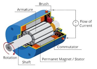
Basically, a DC motor has 4 main parts including:
1. Stator
The stator is the stationary part of the motor, consisting of a magnetic field that is created by the motor’s windings. The windings are made up of a series of wire coils that are arranged around the stator, which is typically made of iron. The interaction between the stator and rotor produces the rotational force that drives the motor’s output shaft.
2. Rotor
At the core of every DC motor is the rotor, the rotating component that produces the motor’s mechanical output. The rotor is typically made up of a wire coil that is wound around an iron core, which is mounted on a shaft. When an electrical current is applied to the coil, it creates a magnetic field that interacts with the motor’s stator, causing the rotor to turn.
3. Commutator
The commutator is another key component of the DC motor, located on the rotor. It is a series of copper bars that are arranged around the rotor and are connected to the ends of the wire coils. The commutator is responsible for reversing the direction of the electrical current flowing through the motor’s windings as the rotor turns, ensuring that the magnetic field continues to interact with the stator in the proper way.
4. Brush
The brushes are another important component of a DC motor, responsible for transferring electrical energy from the power source to the motor’s commutator. They are typically made of carbon, and are positioned to press against the commutator as it rotates.
How DC Motors Work: Understanding the Working Principles Behind Their Operation
DC motors are used in a wide range of applications, from powering household appliances to driving industrial machinery. But how do these motors actually work? In this article, we’ll take a closer look at the principles behind the operation of DC motors, examining how they convert electrical energy into mechanical motion.
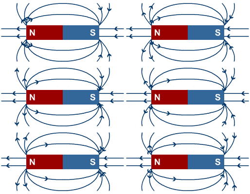
The basic principle behind DC motor operation is electromagnetism. In a DC motor, electrical energy is supplied to a coil of wire, which creates a magnetic field. This magnetic field interacts with another magnetic field in the motor, causing a force to be exerted on the wire. As a result, the wire begins to rotate, producing the motor’s mechanical output.
The interaction between the magnetic fields in a DC motor is made possible by the motor’s construction. Inside the motor, there are two main components: the stator and the rotor. The stator is a stationary part of the motor that contains the magnetic field, while the rotor is a rotating part that contains the wire coil. When electrical energy is supplied to the coil, it produces a magnetic field that interacts with the magnetic field in the stator, causing the rotor to turn.
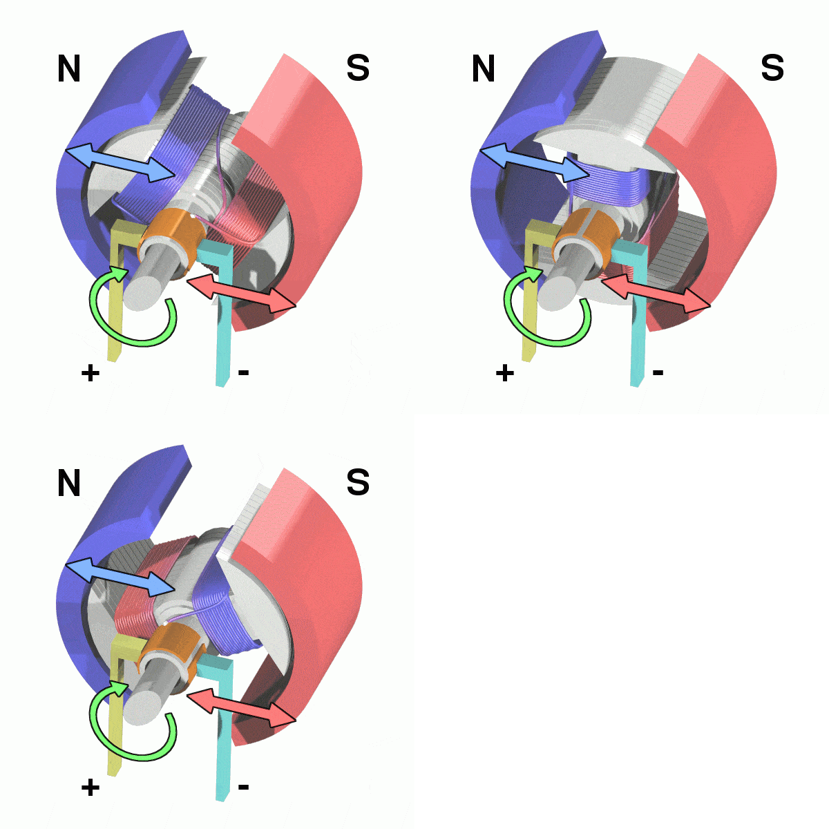
To ensure that the rotor turns in the correct direction, DC motors use a commutator, a component that is located on the rotor. The commutator is a series of copper bars that are connected to the ends of the wire coil, and it is responsible for reversing the direction of the electrical current flowing through the motor’s windings as the rotor turns. This ensures that the magnetic field continues to interact with the stator in the proper way, producing a consistent rotational motion.
The power source for a DC motor is typically a battery or other electrical source that provides a constant flow of direct current to the motor’s windings. This flow of electrical energy is what drives the motor’s operation, allowing it to produce the rotational force that powers the motor’s output.
In conclusion, DC motors work on the principles of electromagnetism, with electrical energy being converted into mechanical motion through the interaction of magnetic fields. By using a combination of stationary and rotating components, along with a commutator to ensure consistent motion, DC motors are able to produce the rotational force necessary for a wide range of applications. Understanding the principles behind DC motor operation is essential to understanding their potential uses in modern technology.
Types of DC Motor Types
1. Motor Brushed
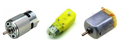
Brushed motor is a motor that has a brush or brushes that can work when given a direct electric current. This type of motor was the first to be developed before other types of DC motors. The brush is connected to the commutator which will change the direction of the current in the motor coil so that the direction of the magnetic force lines on the motor also changes, so that the rotor can rotate in a certain direction.
2. Motor Brushless
Brushless or brushless motors are often also referred to as BLDC (Brush Less Direct Curret) motors. In a brushed motor, the coil is in the rotor and the magnetic field is in the stator, whereas in a brushless motor it is the opposite, the stator is the coil and the rotor is the magnet. This motor rotates by producing an electromagnetic field in the three coils alternately so that the magnets in the rotor will produce rotation.
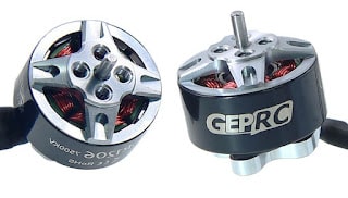
Brushed motors can be operated directly, only by connecting a voltage source. Meanwhile, brushless motors must use an additional circuit which is usually called an ESC (Electronics Speed Controller). This motor is often used on drones or mini boats because it has a high RPM.
3. Motor Servo
Servo motor is a motor that can maintain its position to a certain degree. In brushed and brushless motors, the power source provided will rotate the motor continuously, while the servo motor has an internal circuit that functions to maintain the degree position on the motor.
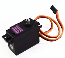
This internal circuit is a digital electronic circuit that has a feedback system. This means that the degree position of the motor will be stored and fed back to the internal circuit to keep the motor in position. Servo motors are usually used in arm applications or robotic grippers.
4. Motor Stepper
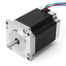
Stepper motor is a motor that rotates based on the specified step. There are two types of steppers, namely bipolar and unipolar steppers. These motors usually have 4 or 5 inputs which will be given digital pulses. This digital pulse will rotate the motor, usually one rotation of this motor must be given 24 steps to 96 steps.
This step is useful for determining how many motor rotations you want. Its application is most widely used in conveyor chains or in 3D printers.
The Relationship Between Torque and RPM in DC Electric Motors: An Overview
When discussing DC motor specifications, the things that many people consider are the torque and RPM. The greater the torque and RPM of a motor, the more reliable the motor is. Then what does torque and RPM mean for a DC motor?
Torque is the power generated by a rotating DC motor. The greater the torque on the motor, the stronger the motor is in lifting the load. Torque is generated by the magnetic flux in the permanent magnets and coils. But usually DC motors have a gearbox to increase the torque. The consequence is, the greater the torque, the slower the RPM.
RPM itself stands for Revolution Per Minute , is the number of rotation cycles on a DC motor every one minute. Motors with high RPM are usually used in electric car drives or robots. Usually, to produce high RPM you have to sacrifice torque, so DC motors that have high RPM generally have low torque.
Driver motor DC
Brushed type DC motors can be connected directly to the voltage. However, in digital-based electronic circuits, the output current is generally only a few milliamperes, so it is not enough to turn the motor. This can be overcome using the Driver series. Some of the drivers that can be used are:
- Driver circuit using transistors
- Driver circuit using MOSFET
- The driver circuit uses the L293D IC
- The driver circuit uses the L298 IC
How to set the direction of rotation of a DC motor? to adjust the DC motor rotation is done by reversing the polarity of the motor input. By reversing the polarity, the rotation of the motor will reverse from clockwise (CW) to counterclockwise (CCW).
With the circuit above, you can adjust the direction of rotation of the motor because all of these circuits use an H bridge configuration. In addition to the direction of rotation, the circuit above can also be connected to a DC motor speed control circuit based on PWM (Pulse Width Modulation).
Advantages of DC motors
- Minimal maintenance
- Low price
- Simple and Easy to use
- Has many types as needed
- Easy to set speed (RPM)
- Fairly large torque
- Minimal vibration
- Efficient energy consumption
Function and Application of DC motors
The main function of a DC motor is as an actuator (drive). DC motor converts electrical force into mechanical movement. Equipment that requires a lot of motion energy that uses DC motors including:
- Wheel Drive in electric cars
- Computer or laptop cooling fan
- Robot Arm
- Vibrating vibrator on smartphone
- Conveyor
- Portable electric drill
- Water pump
- Health ventilator


