Induction Motor is ? Following are the definitions, types, characteristics and working principles of induction motors with examples
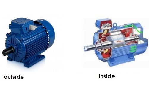
An induction motor, also known as an asynchronous motor, is an AC electric motor that is commonly used in society. So called because these devices operate at a speed less than their synchronous speed.
Then, the need for electric current in the rotor to produce torque is obtained through the electromagnetic induction phase from the rotating magnetic field in the stator winding. Then what exactly is the definition of an induction motor according to the branch of electrical engineering?
Definition of Induction Motor

From an electronics construction perspective, the definition of an induction motor is the simplest electric machine that operates using the principle of induction in which an electromagnetic field is induced into the rotor when the magnetic field rotates.
Technically it can also be said that an induction motor is a type of AC electric motor (reversing) which has a rotor rotation that is not the same as the rotation in the stator field / has a difference in rotation (slip).
Induction motors are also durable in use. This makes it the ideal machine for a wide variety of activities. In fact, it can be operated for years without requiring periodic maintenance.
On the other hand, the speed of an induction motor is relatively static, so it cannot be applied to devices that require dynamic speed. Moreover, the speed control was somewhat difficult. In addition, the initial use of input current is high enough to trigger a more rapid reduction in voltage.
Induction engines are among the most common types of motors used in commercial, industrial, or household settings. This device has the following characteristics.
Characteristics of Induction Motor:
- Simple and sturdy construction
- Low cost and minimum maintenance
- High enough reliability and skill
- No need for additional starter motors and the need to be unsynchronized.
Induction Motor Formula:
In theory it is stated that when the Stator on an induction motor is supplied with electric voltage, an electric current will automatically flow in the stator coil and the result is a magnetic field wave rotating around the stator.
a. So the formula for the speed of the stator rotating field in the induction motor is Ns = 120.f / p:

With:
- Ns : stator rotating field speed (rpm).
- f : frequency (Hz).
- p : the number of poles.
b. Then for the formula for calculating the amount of slip in an induction motor (cage rotor) you can use the following equation:

With:
- S : slip motor.
- Nr : rotor speed (rpm).
c. Furthermore, to calculate the value of mechanical power and torque on an induction motor, we can use the equation below:
Mechanical power:

Torque :

Induction Motor Efficiency :

With :
- Prot : power on the rotor.
- Pmek = Pout : rotor mechanical power.
- T: torso.
- I2 : current in the rotor.
- R2 : resistance on the rotor.
- η : efficiency.
Also Read: Understanding & How DC Motors Work
Types of Induction Motors
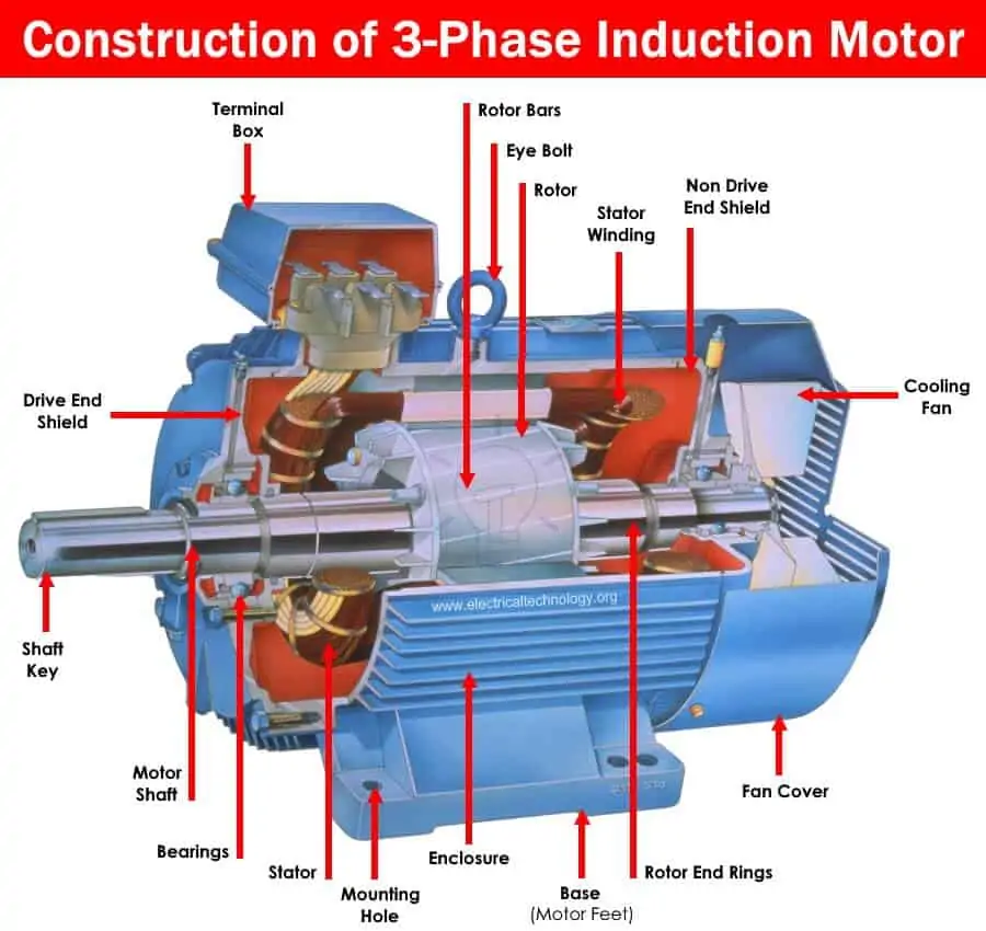
Induction motors are often classified based on their rotor construction. On this basis, there are at least two types that need to be known, namely as follows.
- Wound rotor
The wound rotor is designed to have a coil connected to the star on the inside, while the other end is arranged in the form of a slipring towards the outer resistance. The coil can later be developed so that its speed keeps up with the rotation of the motor.
- Squirrel cage
Located on the inside, this rotor is the free-spinning part of the machine. Usually made using laminated iron material where the stem has a short connected slot at each end.
3 Phase Induction Motor

In a three-phase system, there are three single-phase channels with a phase difference of 120°. So the rotation of the magnetic field has the same phase difference where the whole will drive the rotor to move.
If you consider the three phases a, b, and c, when phase a is magnetized, the rotor will move towards phase a of coil a. Next, phase b will be magnetized so that it immediately attracts the rotor, and then phase c. With this mechanism, the rotor can continue to rotate.
Examples of the application of 3-phase induction motors include elevators, large-capacity exhaust fans, oil extraction plants, textile industries, and the like.
Single Phase Induction Motor

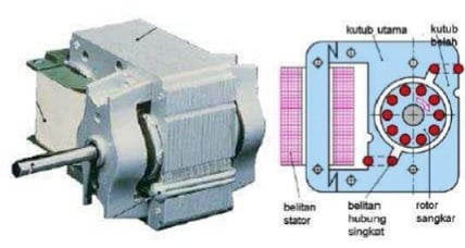
In this type of motor, the starting coil may have a series capacitor and/or a centrifugal switch. When the supply voltage is applied, the current in the main coil lags the supply voltage due to impedance. Meanwhile, the current in the starting coil experiences a supply voltage according to the impedance of the starting mechanism.
The angle between the two coils is sufficient to produce a phase difference to drive the rotating magnetic field so as to produce a torque. When the motor speed has reached 70 percent to 80 percent of the total synchronous speed, the centrifugal switch opens, disconnecting the starting coil.
Examples of the application of single phase induction motors include compressors, mixers, toys, pumps, high-speed vacuum cleaners, electric shavers, and drilling machines.
Induction Motor Function
The main function of an induction motor is as a medium for converting electrical energy into magnetic induction power so that it can produce mechanical motion.
There are basically two types of induction motors where the classification is arranged based on the input supply. There are single-phase and 3-phase induction motors, each of which has different applications, as previously discussed.
But in essence, the type of single phase induction machine is not a motor that can start operating alone, while a 3 phase induction motor works the other way around, it can start operating alone.
Working Principle of Induction Motor
The workings of an induction motor certainly involve an induction process as the name implies. When you provide supply to the stator winding a magnetic flux will be generated in the stator due to the current flowing in the coil. At the same time, the rotor windings are arranged so that each coil is short-circuited.
Furthermore, the flux from the stator will cut the short circuit coils in the rotor. Since the rotor coil is set to short circuit, according to Faraday’s law of electromagnetic induction, current will begin to flow through it. Parallel to this, another flux will be produced in the rotor.
There are now two fluxes, one is the stator flux, and the rest is the rotor flux. The rotor flux will lag with respect to the stator flux. Therefore, the rotor will feel a torque that can make it rotate in the direction of the rotating magnetic field.
Examples of tools that use induction motor applications are easy to find in everyday life, both in the industrial sector and meeting household needs.
This device offers a number of advantages, such as relatively cheap price, high level of efficiency, and low maintenance costs. That’s what wikielektronika.com can provide regarding information about induction motors. Hopefully it can provide benefits!


