If you are familiar with the world of electricity, you must be familiar with an ammeter, right? Where this one measuring instrument has a somewhat important role in electricity needs.
An ammeter can measure how much electric current flows in the circuit. So, the size of the strong current in the electrical network can be read using this one tool.
Let’s find out more about what an ammeter is. It is not only about the general understanding but also the function, how to work, and how to use and read it.
Check out more information in the following article!
Definition of Ammeter
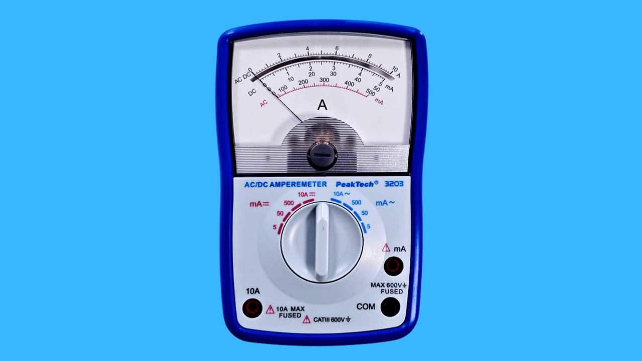
An ammeter is a tool used to measure the level of electric current in a circuit.
In general, ammeters are made of shunt resistance and microamperemeters arranged in series. The function of using a shunt and microammeter is to detect the level of the size of the electric current voltage contained in the circuit.
An ammeter will make it easier for technicians to check the electrical network. This is because you know the size of the strong current flowing in it.
Ammeter function

In general, the ammeter’s function is to detect the electric voltage. However, the ammeter can only function to measure electric current in a closed circuit.
To measure current, ammeters are usually connected in series and must be connected to a shunt resistance.
The function of installing shunt resistance here is so that the ability of the tool to make measurements is more remarkable.
Parts of the Ampere Meter
To know more about the ammeter-type measuring instrument, you also need to know the parts of the ammeter.
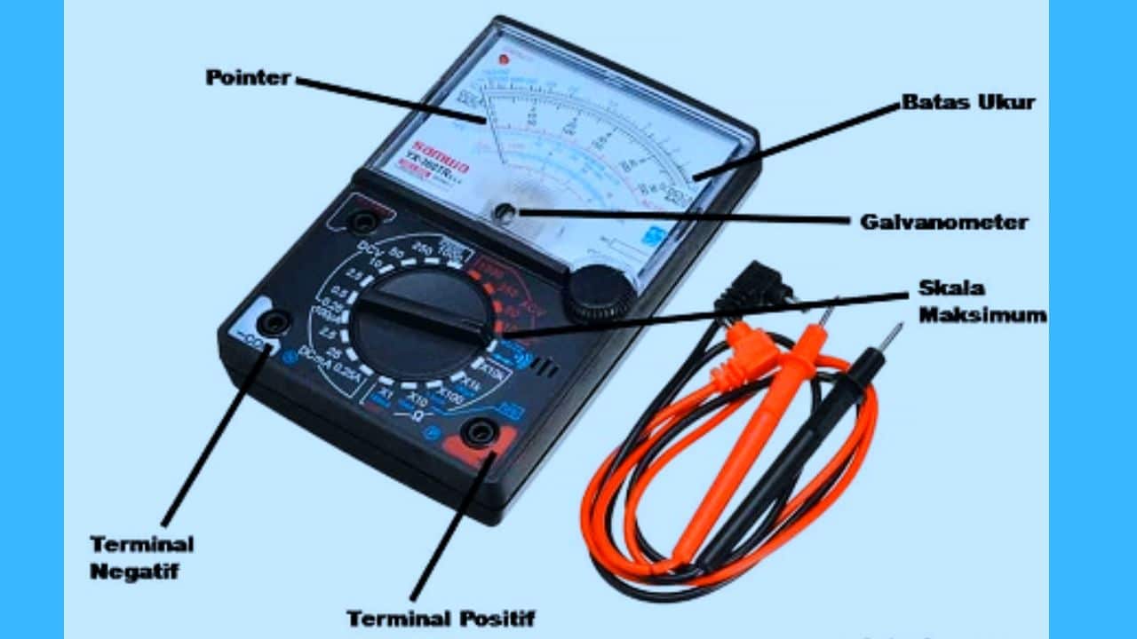
The parts that make up the ammeter are :
- Galvanometer.
- measuring limit.
- Positive and negative terminals.
- Pointer or pointer.
- Maximum scale.
- shunt resistance.
Check out a more detailed explanation of each ammeter section below.
- Galvanometer
The galvanometer is the main component of the ammeter, whose function is to measure the level of electric current. More interestingly, this component has been tested to carry out measurements with high accuracy.
This component also consists of several layers, namely an iron core, then covered by a coil made of very fine wire.
The galvanometer components are arranged in series with resistors and resistance in the ammeter. The goal is that the measurement limit it has becomes larger.
The galvanometer works with the Lorentz law system. When an electric current flows through the coil or coil, the iron core will be a magnet and attract.
Furthermore, the iron core will rotate, automatically making the pointer start moving. After measuring, the needle will stop on the scale on the display screen.
- Measure Limit
The measuring limit is the maximum value contained in each ammeter. This maximum value will later show the highest value that can be measured using an ammeter.
- Positive and Negative Terminals
The ammeter also has a component called the positive terminal and the negative terminal. The positive terminal functions for positive input, while the negative terminal is used for negative output.
- Pointer Needle or Pointer
The pointer needle is often referred to as a pointer. This is because its function is to show the value of the measurement results on an analog-type ammeter.
Because in the digital version, the measurement results are indicated by numbers, so there is no need for a pointer as part of the ammeter component.
- Maximum Scale
Maximum scale serves to display the highest value limit. At full scale, there are several methods used to read ammeters. If you measure current strength, the ammeter reading method will scale the value from left to right.
Meanwhile, if measuring the value of resistance or resistance, the method of reading the value scale is seen from right to left.
- Shunt Resistance
The next ammeter component is the shunt resistance, where the shunt resistance is part of the ammeter, which is used to create a resistance path.
This is so that the electric current contained in the circuit allows it to continue flowing to other points.
The shunt resistance is installed to increase the measuring limit and widen the deviation. The resulting resistance value is equal to or less than 1 ohm.
How Ammeters Work
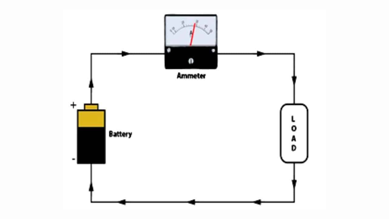
The workings of the ammeter are by a system of magnetic force and Lorentz force. In general, there will be layered coils.
This coil can later work by utilizing the magnetic field generated by the electric current in the ring.
The way the ammeter works is as follows:
- When the ammeter is energized with an electric current, this will trigger a magnetic field.
- Electric current flows through the coil; it will arrive at the iron core and cause a magnetic reaction on the component.
- The magnetic field will make the iron core rotate, then the pointer will automatically start moving until it stops at the point on the scale that corresponds to the measurement result.
- The user can see the report on the results of this measurement on the ammeter display screen.
- To increase the ability of the ammeter to perform ammeter measurements, it is also possible to add a shunt resistance.
- The purpose of this barrier line is to increase the resulting deviation to expand the tool’s measuring limit.
- Because the more significant the current flows, the wider the deviation. Thus, automatically the measuring limit on the ammeter will also be higher.
Ammeter Type Based on Reading Method
The type of ammeter, of course, continues to experience version development. Every kind of ammeter will have its specifications and how it works.
The types of ammeters based on the reading method can be divided into 2, namely:
- Analog Ammeter.
- Digital Ammeter.
You can see the full explanation below to determine the difference between the two types of ammeters.
1. Analog Ammeter
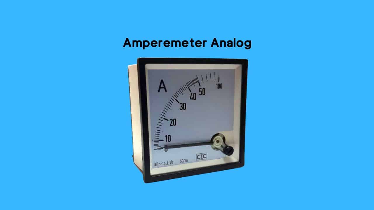
The analog version of the ammeter is a measuring instrument whose reading method is seen from the scale indicated by the pointer. Analog ammeters are also divided into two.
- AC ammeter
- DC ammeter
The discussion regarding the two types of analog ammeters is as follows:
- AC ammeter
This analog ammeter is a measuring instrument used for AC power circuits and is usually installed using a series arrangement.
- DC ammeter
DC ammeter is a tool used to measure DC voltage. It is still the same as the previous one; this tool must also be installed in series when measuring.
2. Digital Ammeter
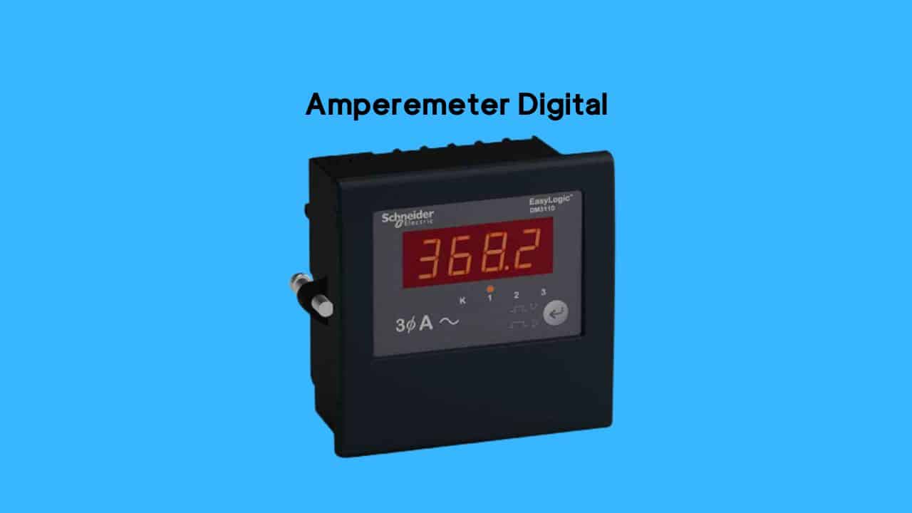
Unlike the analog version, how to read a digital ammeter can see directly the measurement results in the form of numbers.
So, reading the measured value on a digital ammeter is relatively easy. This is because users only need to see and read the numbers on the display.
Types of Ammeters Based on the Working System
Apart from the method of reading, the type of ammeter is also distinguished by its working system.
The following is a discussion of the various types of ammeters based on how they work:
1. Hooks
This type of ammeter with a hook type has several advantages. One of them is because it is considered easier to use.
The hook can be used to measure any alternating current. In addition, it is also more practical because it can take measurements instantly.
So when taking measurements, the user does not need to open or disturb the circuit first.
This is because the hook can be used directly by attaching it to the object to be measured. How? Very practical and easy for users.
2. Electromechanical
The electromechanical type works with an electromechanical system. So the measurement is done by looking at the mechanical interaction between the current and the magnetic field.
In addition, mechanical interactions can also occur in conductors that carry an electric current.
2. Thermal
This type of thermal ammeter works with an expansion system by looking at the expansion contained in the conductor.
So the degree of heat generated in the thermal will be proportional to the square of the current in the circuit.
How to Use an Ammeter
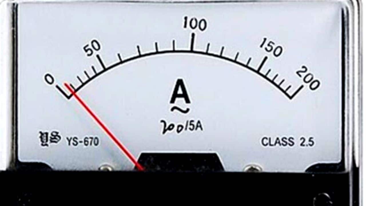
If you are not used to taking measurements using an ammeter, many people need help understanding how to read an ammeter.
To find out more about using ammeters, there are several ways to read ammeters that you can do.
Check out the following explanation:
1. How to use an ammeter without an amperage clamp
For ammeters, it turns out that some are using clamp amperes, and some are not. For versions without clamp amperes, this is usually found in ammeter types with analog versions.
Here are some steps to read the current value using an ammeter without an amperage clamp:
- First, the ammeter is connected in series with the load.
- Start adjusting the knob according to the closest estimate of the measuring limit. Also, change the type of object that will be measured.
- Determine the measuring limit range, then rotate the knob found on the tool.
- Turn on the voltage source, then watch the pointer’s movement on the display.
- How to read an ammeter to find out the measurement results; pay attention to what value is shown by the pointer.
2. How to use an ammeter with an ampere clamp
Clamp amperes are usually found in digital-type ammeters. The advantage of this digital type is that you can continue taking measurements without disconnecting the electrical circuit.
So, the tool can be directly attached to the cable when measuring its electric current. Consider the steps using the following digital ammeter:
- To make measurements, first adjust the range with the appropriate approximate measuring limit.
- Place the cable in the circuit that will be measured later.
- Then, on the display will appear a number that determines the measurement results.
Conclusion
An ammeter is a tool used to measure the level of electric current flow. Based on the reading method, ammeters are divided into analog and digital versions.
The operating system requires a series of installations along with a shunt resistance.
The purpose of this kind of installation is to make the measuring limit of the tool wider and the measurement capability to increase.
That’s a discussion of ammeters starting from their understanding, functions, how to work, and tutorials on how to use and read them. Hopefully, the reviews above are pretty helpful, huh?

