The power amplifier circuit is an electronic circuit consisting of passive components and an amplifier that functions to amplify the input signal.
The input signal in question is sound coming from a microphone, radio frequency or from a digital file that is converted to an analog signal.
The components used in the power amplifier circuit are active components such as transistors. The transistor in the amplifier circuit works in the active region, between saturation and cut-off.
Amplifier circuits are built using several different systems. The most popular systems include Output Transformer Less (OTL), Output Capacitor Less (OCL) and Bridge Tiel Load (BTL). The diagram below uses the OCL system.
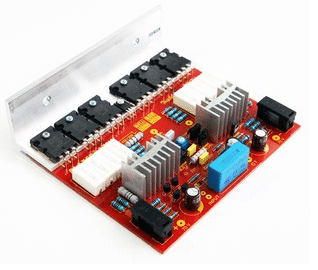
What is OCL?
OCL is an amplifier system where the circuit does not use a capacitor as a coupling and filter at the amplifying output. Usually, capacitors are installed before the circuit is connected to the speakers as coupling and protection against signals that might damage the speakers.
The amplifier with the OCL system has a wide frequency response so that the audio frequency range can be produced properly. Powered by a final transistor with a Push-Pull configuration providing maximum amplification of the sound signal produced.
But behind its advantages, the OCL system has a weakness, namely if one of the final transistors is damaged (short circuit), then it is possible that the speaker will also be damaged.
Even so, this can be overcome by buying components with quality brands and using a speaker protector.
Mono and Stereo Amplifier Circuits
A mono amplifier is a circuit whose input is a single phase signal where the audio inputs are mixed together and amplified in one amplifier circuit. Usually mono circuits use a single speaker.
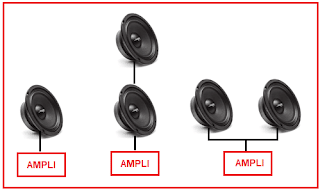
Although in practice two or more speakers can be in series or parallel, in reality the sound produced remains the same on each speaker. Examples of mono speakers can be seen on old FM radios.
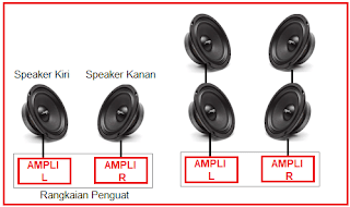
It’s different with the Stereo amplifier, where the signal phase is separated between R and L so that it uses 2 speakers. The Stereo Circuit produces a more natural sound because the output signals between the R and L of the Speaker are different, creating a realistic sound feel. An example is the speakers in a movie theater or performance theater
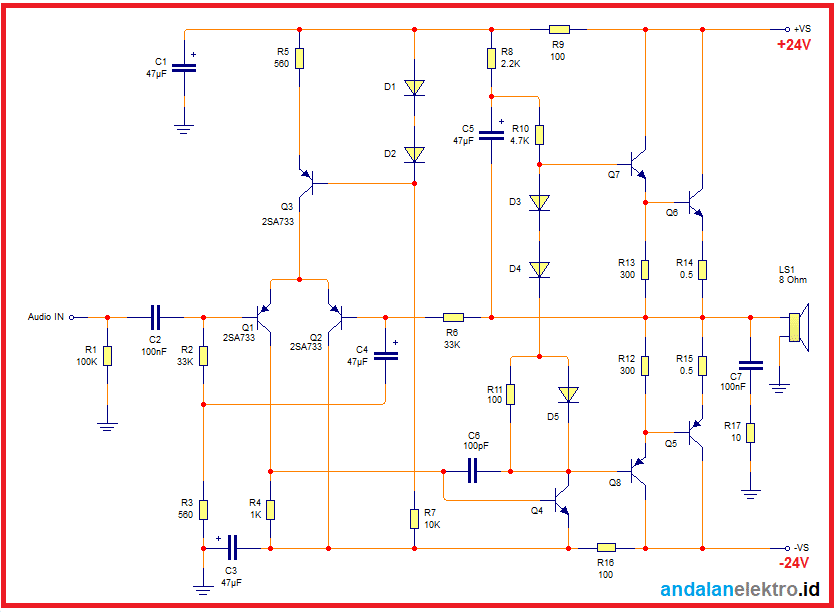
List of components used
A complete explanation of the list of components used and their descriptions can be seen in the table below

Notes :
The diagram and list of components above is a series of mono alias single speakers. If you want to use stereo speakers, you have to use 2 mono circuits for the R and L speakers.
The final transistor used may be of the type MJ2955/MJ3055 or TIP2955/TIP3055
Power Supply
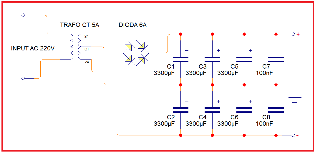
The power supply used in the OCL amplifier circuit uses a symmetrical type with plus (+), ground and minus (-) outputs. The power supply circuit can be seen in the image below:
Tips on making amplifier circuits
- Use genuine and quality components. For example, the resistor uses metal film material with a tolerance of 1% and the final transistor uses the original ST component.
- Use a pure 5A transformer and its large capacitance filter capacitor, resulting in low ripple. The ripple voltage will affect the sound quality.
- It’s best to use a Speaker Protector to protect the speakers from damage due to a short circuit in the amplifier circuit.
